Pinecil case

Work in progress

Open the lid.
There is a bench inside.

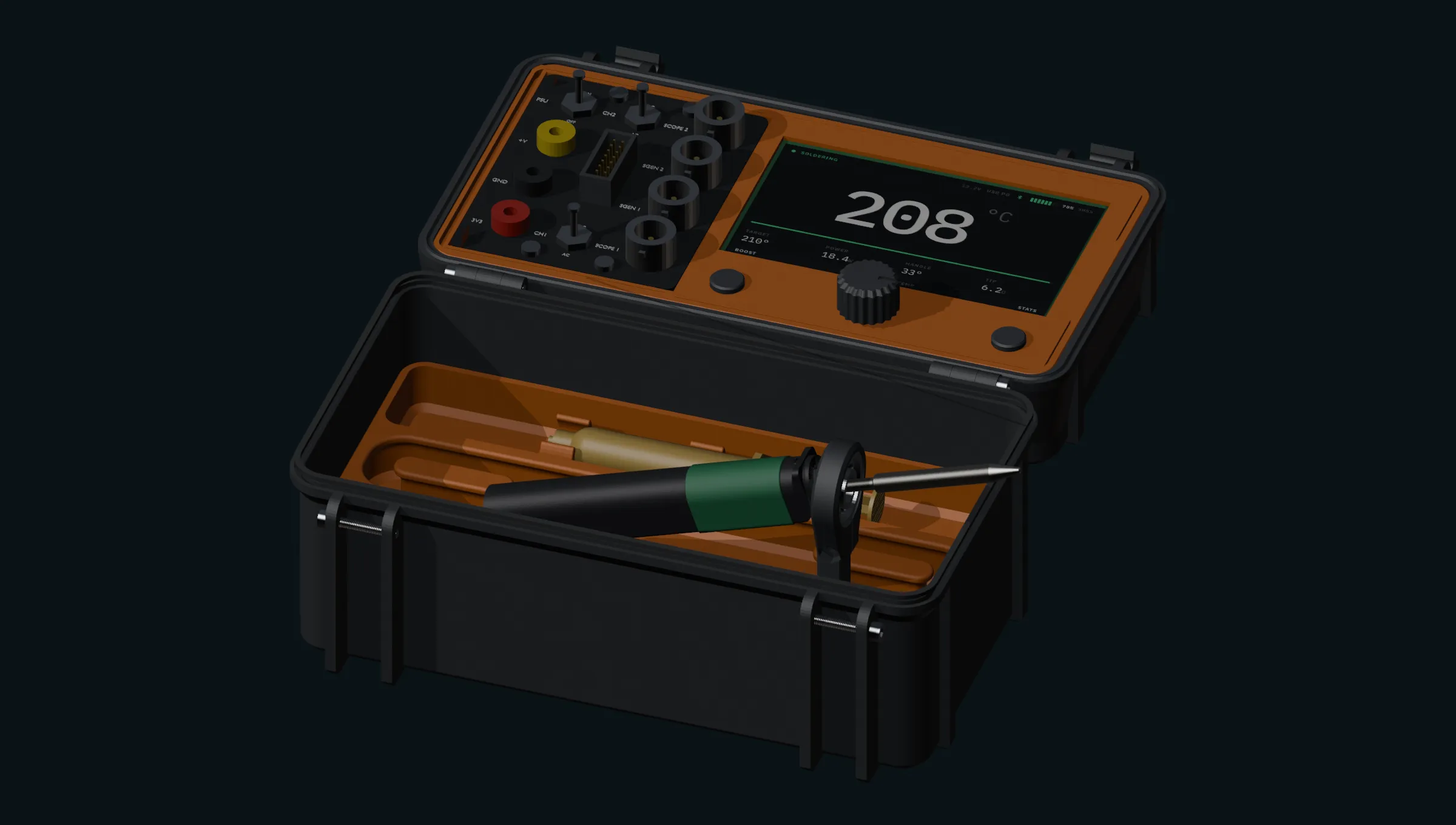
A rugged printed carrying case for the Pine64 Pinecil, with the lid turned into a portable instrument panel. A 4.3 inch touchscreen where the empty ceiling used to be, and an EspoTek Labrador behind it: two channel scope, waveform generator, logic analyser, bench supply and multimeter.

The model below is the real assembly, in your browser. Drag it around, and switch between the eight configurations it holds.

The case open on a bench, the lid carrying a 4.3 inch display reading 208 degrees C, the soldering iron docked nose-down in a printed stand that rises out of the upper tray.

Open, stand deployed out of the tub, iron docked through the 608 bearing at 19.29 degrees. One 3.5 MB file carrying all eight keyframed configurations as a baked animation, exported from the same assembly as every image on this site. The geometry it embeds is third-party, licensed CC BY-NC-SA 4.0, non-commercial use only.

01 / the idea

A soldering iron needs a case. A case has a lid. A lid, once it swings past 90 degrees, is a flat surface pointing at the person using it, with 12 mm of unused depth behind it. That is a front panel nobody was using.

A case that already works

A rugged printed shell, 194.6 by 119 mm and 78 mm tall shut, with two stacked trays inside. One carries the iron, its tips, a flux syringe and a solder reel. The other carries the stand, which lifts out and works on the bench with the case nowhere near it.

2 trays · 8 configurations · audit clean

A screen in the lid

A 4.3 inch capacitive touch panel recessed into the lid's inner ceiling, with an encoder and two softkeys beside it. The hinge swings a full 180 degrees, so the lid flips right over and the instrument face is the surface looking back at you.

Waveshare ESP32-S3-Touch-LCD-4.3

Instruments behind it

An EspoTek Labrador, 36.8 by 34.7 mm of board, brings a two channel scope, a two channel waveform generator, a two channel logic analyser with serial decoding, a 4.5 to 15 V supply and a V/I/R/C meter. Jacks on the lid face, the board behind.

scope · AWG · logic · PSU · DMM

02 / why the inside of the lid

The protected face is the useful one

The obvious place for a panel is the outside of the lid. It is also the wrong one. A rugged case should not carry BNC barrels proud of its outside, and anything mounted there is exposed exactly when the case is shut and being carried.

Because the hinge goes the full 180 degrees, the lid's interior is what faces up in use. A display recessed into the ceiling therefore looks at the operator while working and is fully enclosed when shut, protected by the case's own geometry rather than by an added cover. Nothing in the tub can reach it either: the tallest thing stowed below tops out 24.6 mm short of the glass.

Lid cavity, measured
Clear interior92.0 × 180.0 mm
Outer skin thickness1.20 mm
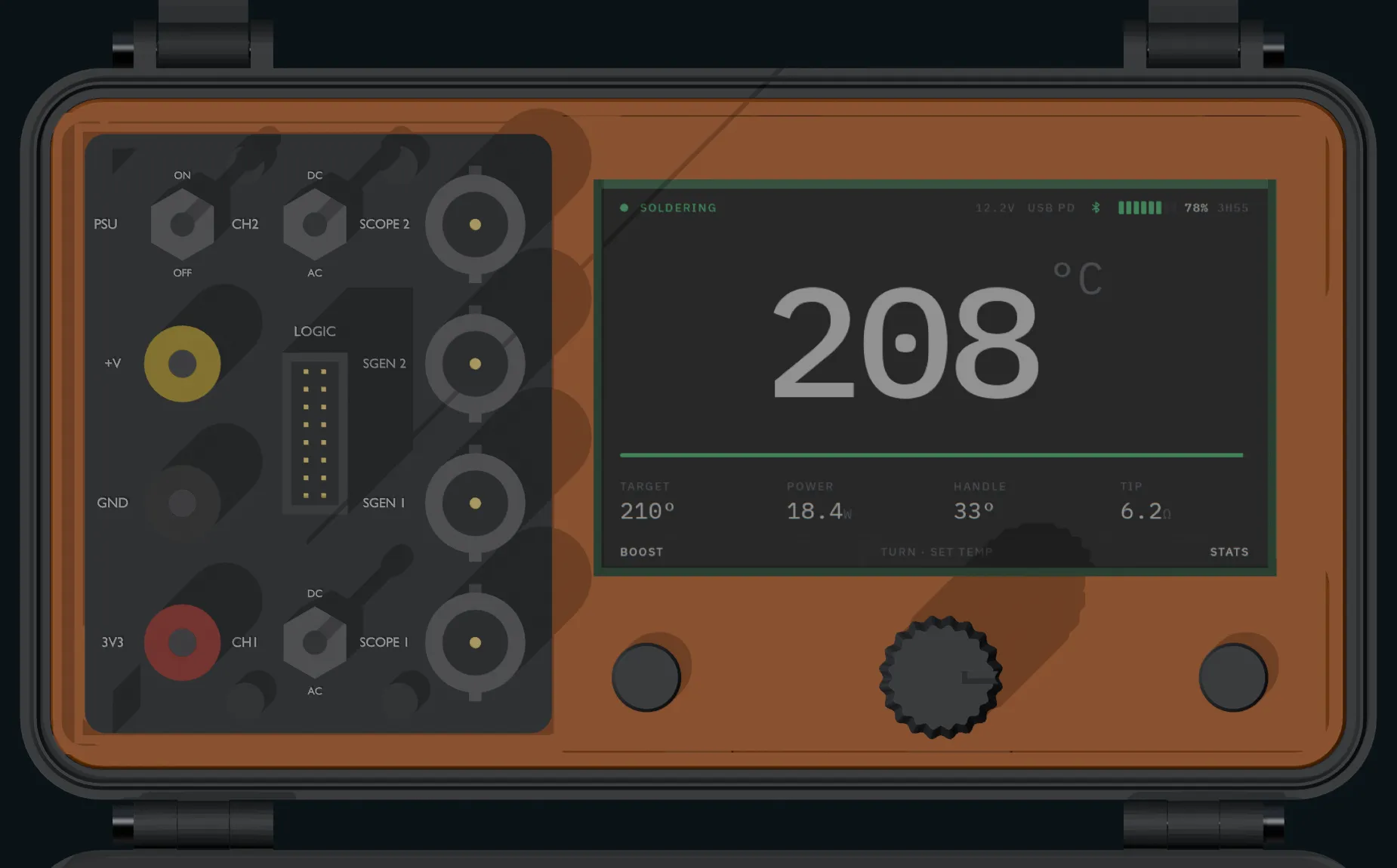
Display active area95.54 × 54.36 mm
Carrier window98.05 × 57.05 mm
Clearance to tub contents24.60 mm
Straight down on the open lid, showing the recessed display reading 208 degrees C, the encoder knob and two softkeys beside it.
stowed openStraight down on the lid. The panel is recessed into the inner ceiling, so it faces you when the lid swings over.

03 / it comes apart

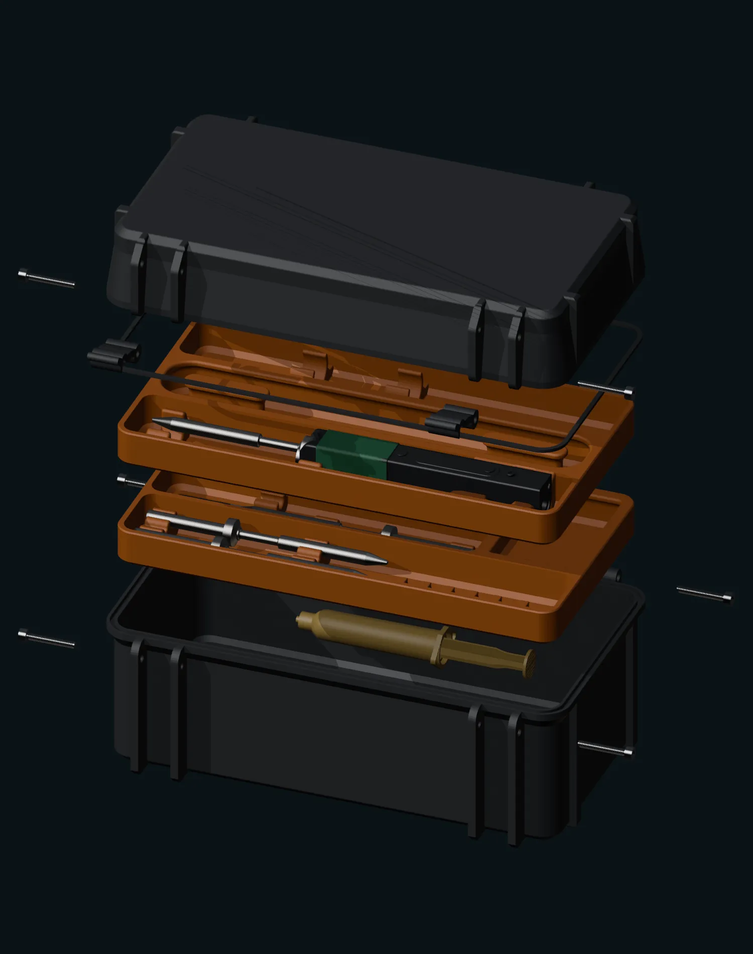
The whole case drawn apart vertically: tub at the bottom, then the lower tray, the upper tray carrying the iron, and the lid assembly floating above.
explodedThe whole stack drawn apart: tub, lower tray, upper tray, lid.

Two trays, one lid, nothing loose

The tub takes a stacked pair of trays. The lower one holds the stand flush in its floor; the upper one holds the iron in a snap cradle with the tip clipped alongside, and lifts straight out. Above both there is 24.11 mm of headroom to the rim, which is what lets the lid carry electronics instead of foam.

The whole assembly lives as one set of parts with eight keyframed configurations layered over it, from shut to fully exploded. An interference audit runs across all eight and currently reports zero unexpected contacts, so a part that would foul something in use shows up before anything is printed.

That is also why the pictures on this site are not photographs or hand staged scenes. Every one is rendered headless from the same assembly, from a committed shot list. Move a tray and the images follow.
04 / what travels with it

Everything the iron needs, and nothing rattling

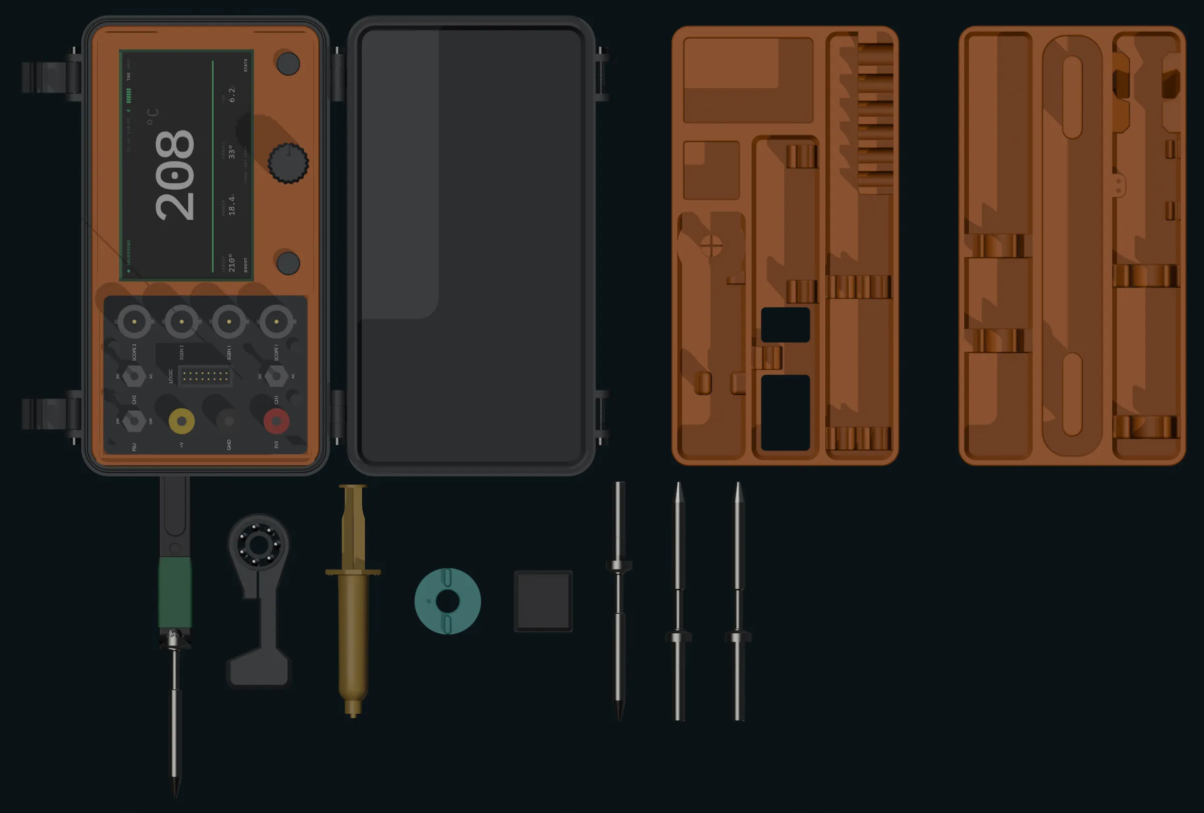
Iron and tip, three spare tips, the 608 skate bearing that forms the stand's ring, the stand itself, a flux syringe, a solder reel on its own spool halves, and a TPU item lid over the small parts. Each has a cavity cut for it rather than a slot it happens to fit.

Flat lay from directly above: the lid, the empty tub, and both trays in a row, with the iron, bearing, stand, flux syringe, solder reel, item lid and three spare tips laid out in front of them.
inventoryEvery item lifted out and laid in front of the trays.
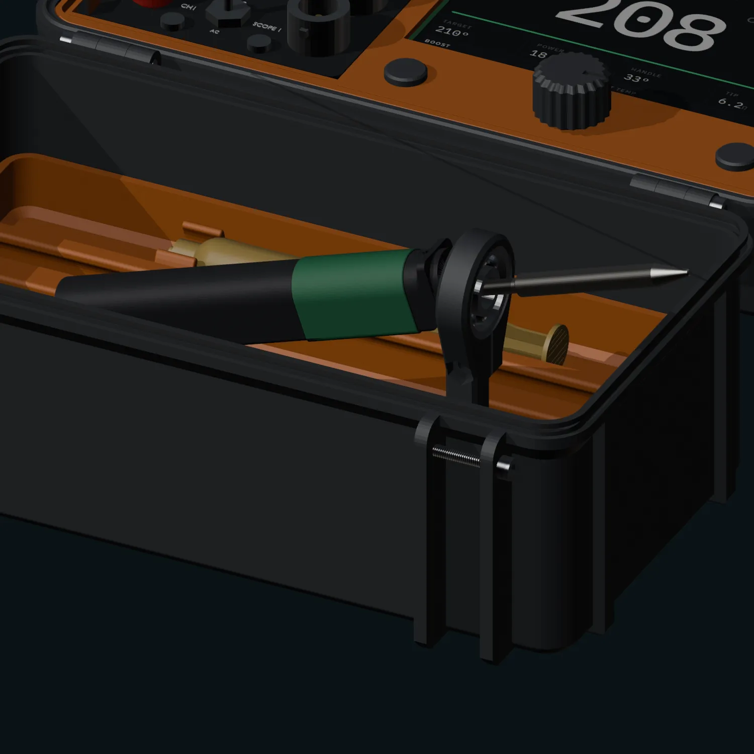
Close view of the iron resting nose-down in the printed stand, its barrel wedged into a 608 skate bearing that forms the ring.
in useA 608 skate bearing is the ring. The barrel wedges into the 8 mm bore and seats on the collar.

05 / the stand

A skate bearing, used as a ring

The iron does not sit in a holster. It wedges nose down into a 608 bearing pressed into the stand's head: the 8 mm bore against a 5.55 mm barrel over a 7 mm width puts the iron at 19.29 degrees, resting on its collar, with the hot end hanging clear off the end of the case. The bearing turns, so the iron can be swung aside without lifting it out.

The stand blades into a ramped socket in the upper tray, which means it works with the tray on the bench and the case shut, open, or in another room.

06 / where this is up to

Honest status, because half of this is still a question

The case half is real and measured. The instrument half is a plan with some of its hardest questions still open. Both are more interesting stated plainly than dressed up.

Settled

  • The case and trays are modelled and audit clean at zero unexpected interferences across all eight configurations.
  • The display is mounted and verified. The window is 98.05 by 57.05 against a datasheet active area of 95.54 by 54.36, centred to within 0.075 mm, with a bezel lip retaining the panel.
  • The board has real retention. Four M2.5 standoffs on the board's own 98 by 60 pattern, through bosses, with the heads counterbored 0.10 below the lid's seating face.
  • The Labrador's pinout is extracted from its own KiCad board rather than read off a wiki diagram, including which pins are the same copper node.

Open

  • Whether the ESP32-S3 can host the Labrador. Stock firmware is isochronous and will not fit the S3's USB host. A bulk-transfer firmware variant exists and suits it on paper, at roughly 832 bytes per millisecond. Unproven on hardware while the RGB display is also hammering PSRAM.
  • The panel layout. A first attempt put jacks where the carrier turned out to be ribs 5 to 9 mm wide. Four of thirteen items had the depth they needed. The carrier is our own part, so it gets material added, but the layout is not final.
  • Connector selection. Real panel mount BNCs and toggles are far larger than the placeholders currently in the model, 33 to 36 mm against 10 to 12. Part numbers and depth behind panel still to pin down.
  • Wiring. Nothing yet routes from the panel to the Labrador, and the Labrador itself is not modelled in the lid. It has no mounting holes at all, so it needs a socket strip carrier for its fourteen header tails.

07 / standing on other people's work

The case is not ours

The shell, the trays, the latches and the stand all come from published designs by PjotrStrog, iamdrew and kriscovery, with a reference flux syringe by Atiesh. They are licensed Creative Commons, non commercial, share alike. Everything on this site that is ours sits on top of that: the Blender assembly, the build and audit scripts, the lid electronics and the fitment work.

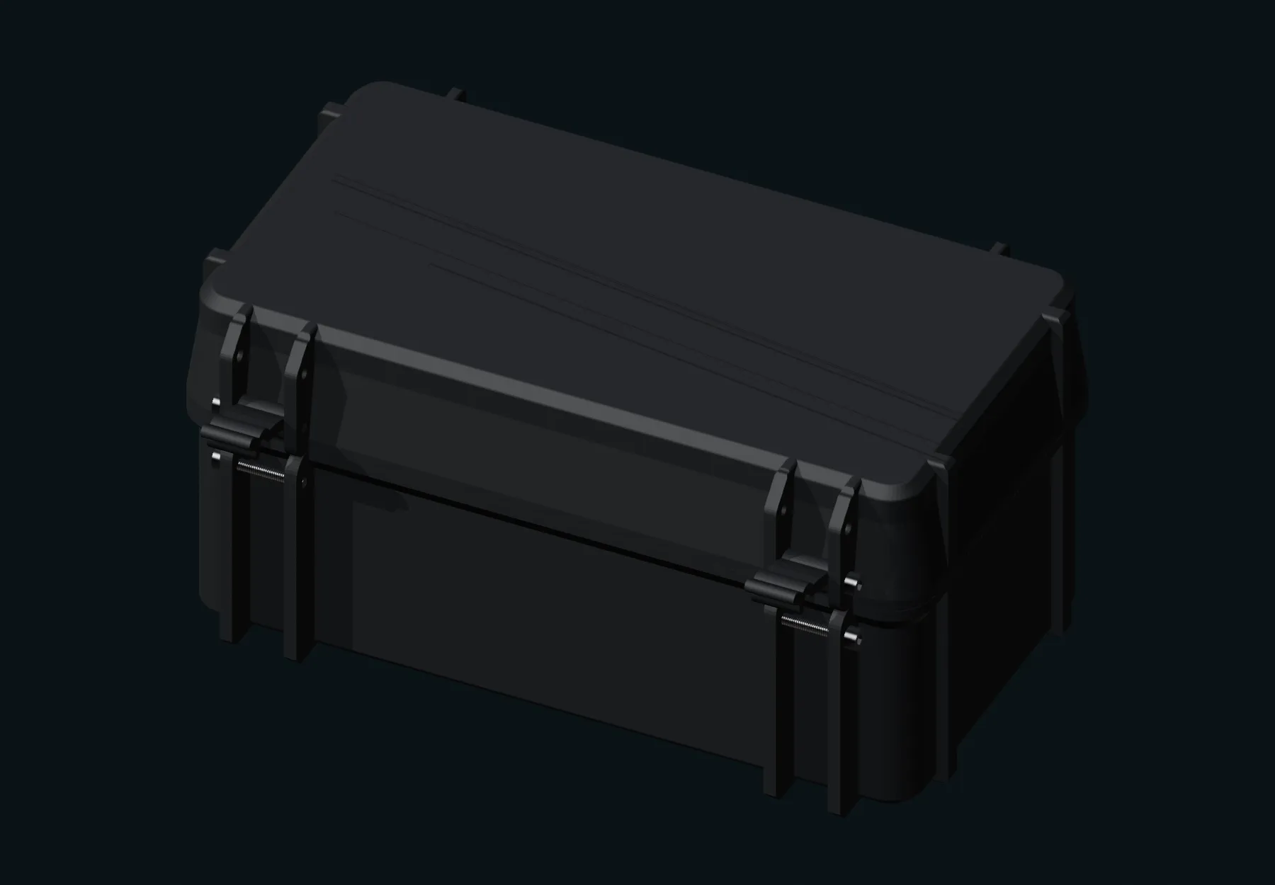
The case shut: a rounded rectangular printed shell with a latch at each end and a hinge along one long side.
stowed closedShut. Two latches, four M3x20, and an optional TPU seal.