hardware
Three pieces, and one of them is a bet
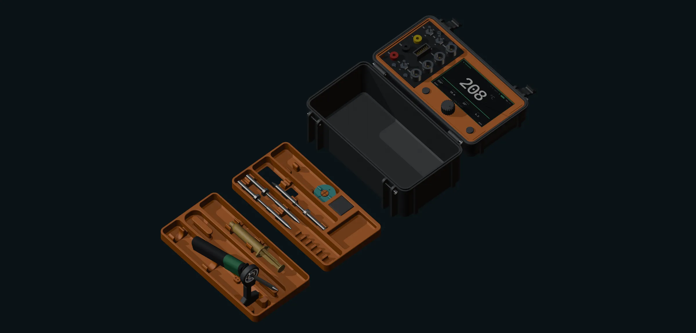
An iron, a display board, and an instrument board. The first two are settled and measured. The third is the interesting one, because getting it running means a USB host stack that nobody has written yet.
the iron
Pine64 Pinecil
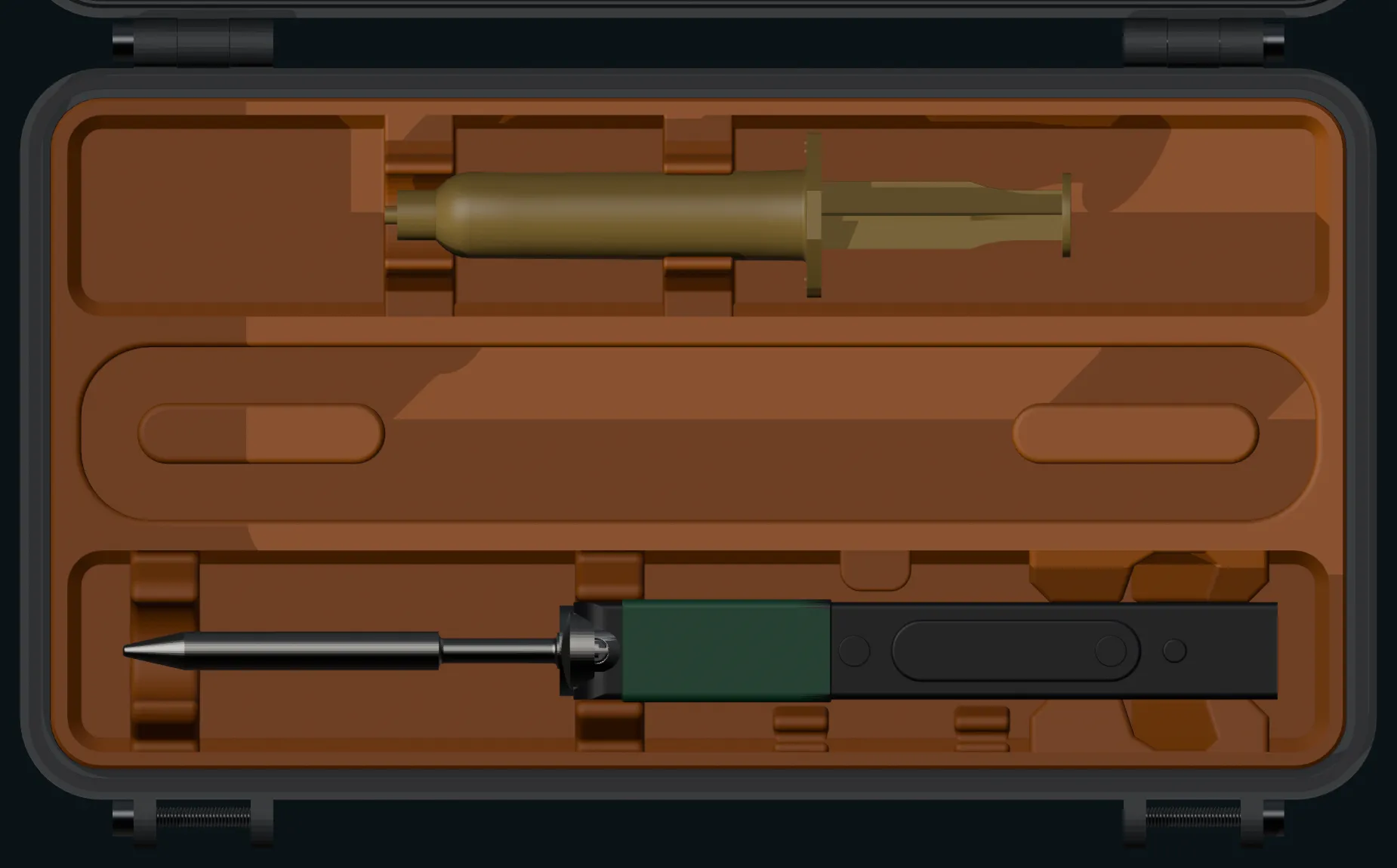
A USB-C PD soldering iron running IronOS on a RISC-V microcontroller. The V2 is the shorter of the two overall despite the longer body, because it ships a shorter tip. Every cavity in this case is cut to these numbers, so they are worth having in front of you.
The tips are ST-B2 type, 86 mm long and 8.2 g each. Size a tip holder for the 86 mm V2 tip and it will still take a V1 tip.
| V2 | V1 | |
|---|---|---|
| Length with tip | 155 mm | 170 mm |
| Length without tip | 103 mm | 98 mm |
| Cross section | 12.8 × 16.2 | 12.8 × 16.2 |
| Weight with tip | 28 g | 30 g |
| Power | 12–24 V, 88 W | 12–21 V, 65 W |
| Barrel jack | DC5525, 3 A min | DC5525, 5 A |
| MCU | BL-706 | GD32VF103TB |
Source: Pine64 specifications.
the display
Waveshare ESP32-S3-Touch-LCD-4.3
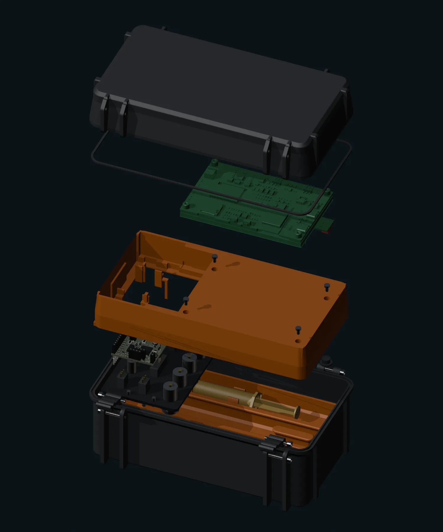
An 800 by 480 capacitive touch panel with an ESP32-S3 on the same board, which is why it is both the screen and the brain. It drops into a printed carrier that reuses the lid tray outline, so the lid shell stays a simple part and the whole display assembly comes out as one piece for service.
It is retained properly rather than glued. The board carries four M2.5 standoff posts on a 98 by 60 pattern and the carrier already had clearance holes in its back skin over every one of them, which took a while to notice: the mount that looked like it needed inventing was already there. What was missing was 1.80 mm of material between post top and skin, so each one got a boss, and the screw heads are counterbored 0.10 below the lid's seating face. A head standing proud there would hold the carrier off the lid.
| PCB overall | 106.0 × 68.0 mm |
|---|---|
| Active area | 95.54 × 54.36 mm |
| Thickness with display | ~8.80 mm |
| Carrier window | 98.05 × 57.05 mm |
| Window centring error | 0.075 mm, both axes |
| Interface | 800×480 parallel RGB |
Beside the display there is a control zone 91.0 by 71.3 mm carrying an encoder and softkeys. It works because of where the iron happens to stop: with the lid shut, the tallest thing under the controls is a tip at 38.29 mm, leaving 23.20 mm for an encoder shaft to hang into the case. The iron's handle is taller but sits under the display, not under the controls.
the instruments
EspoTek Labrador
An open hardware USB instrument the size of a large postage stamp, which is the entire reason this fits in a lid at all.
| Oscilloscope | 2 ch, 750 ksps |
|---|---|
| Waveform generator | 2 ch, 1 Msps |
| Logic analyser | 2 ch, 3 Msps, serial decode |
| Power supply | 4.5–15 V, 0.75 W, closed loop |
| Multimeter | V, I, R, C |
| Board | 36.805 × 34.722 mm |
|---|---|
| Substrate | 1.6 mm FR4 |
| Mounting holes | None. Held by header tails. |
| Overall height | ~20.6 mm with tails |
| Controller | AVR, no FPGA. USB bulk transfer. |
| Power | Bus powered, declares 500 mA |
Its normal host is a Qt desktop application, which is no use inside a lid. What makes this plausible is that the project also ships a portable library separate from the GUI, and that the authoritative pin definitions live in the KiCad board files rather than in a wiki diagram. The pinout used here was extracted from those files, which matters: several pins that look like separate inputs are the same copper node, and one pair sits behind a coupling capacitor.
That detail decided the panel. The board has two scope channels, not four, so two jacks per channel would read the same channel and load each other whenever both were in use. The panel is two scope BNCs each with its own AC/DC coupling switch, two generator BNCs, binding posts for the supply, and one 2×8 IDC header carrying the digital outputs and the logic inputs.
That header started as three separate pin strips, one each for the digital outputs, the generator and the logic inputs. Moving generation onto its own BNCs left six logic signals, and six signals fit one ribbon. One connector, one cable, and a ground beside every channel instead of three strips of flying leads.
the open question
Can the ESP32-S3 actually host it?
Conditionally yes, and not yet proven. The stock firmware is isochronous and cannot work: one variant's 1023 byte isochronous endpoint exceeds the largest packet the S3 host can take in, and the other needs six isochronous pipes plus control, which is all eight of the S3's channels.
A fork adds a bulk interface sending a 64 byte header plus a 768 byte payload per millisecond frame, about 832 bytes per millisecond, or roughly thirteen of the nineteen bulk packets a full speed frame holds. That shape suits the S3. What is unproven is whether the ESP-IDF USB host sustains it while the RGB display is hammering PSRAM. A dropped frame is at least measurable, as a skipped sequence number.
On our side the groundwork checks out. Native USB is routed on the Waveshare board and the serial console does not eat it, because the bridge is a separate chip on its own pins. There is a mux in the USB path whose select line hangs off an I2C expander rather than a GPIO, which is worth knowing before debugging: an uninitialised expander leaves the mux pointing the wrong way, and that presents as a dead host stack rather than as a mux fault.
printing it
Nothing exotic
The underlying case prints at 0.2 mm layer height and needs two latches, M3x20 screws through the hinge and latch bores, and an 8 mm skate bearing for the stand. The TPU seal is optional and only buys you a water tight case. The publisher found the inserts a tight enough fit in the shell that glue was not needed.
One warning worth repeating from upstream, because it is easy to get wrong: the V1 and V2 generations of that case do not mix. Every V2 part is compatible with every other V2 part. Pick a generation and stay in it.
Beyond that, this project adds its own parts that have not been printed yet, so treat the above as what the case underneath needs rather than as instructions for building what is on this site.